How it works

Nine stages, each checked before the next begins.

Each stage reads what came before, validates its output and records its links.

One brief, nine artefacts, one chain.

The run stops after stage 02 so you approve the decomposition first.

ASYST · The pipeline

The ASYST pipeline: brief in, traceable model outThe brief feeds nine stages run in order: 01 context, 02 subsystems, an approval gate, 03 requirements, 04 functions, 05 risks, 06 V and V, 07 components, 08 traceability and 09 the Need Analysis, exported as DOCX or PDF. Each stage reads what the ones before it produced. BRIEF 01 Context 02 Subsystems 03 Requirements 04 Functions 05 Risks 06 V&V 07 Components 08 Traceability 09 Need Analysis approval gate DOCX · PDF each stage checked before the next

01The brief becomes a bounded system.

Stakeholders, needs, environment and constraints, and a boundary stated before any requirement exists.

  • Produces a system context record and a stated boundary
  • Standard INCOSE SE Handbook, stakeholder needs and requirements definition

Model · 01 System context
Stage 01 model: system contextA dashed system boundary around the system in scope. Two actors outside it, an operator and a maintainer, and an external ground system, each connected to the system by an interface arrow. Constraints, environment and mission phases are recorded with it. System boundary SYSTEM in scope ACTOR operator ACTOR maintainer EXT ground constraints · environment · mission phases
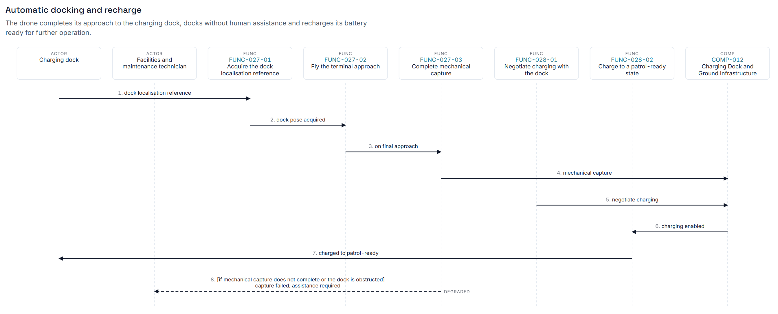
An ASYST scenario diagram titled Automatic docking and recharge: two actor lifelines, the charging dock and a maintenance technician, alongside six numbered functions from FUNC-027-01 to FUNC-028-02 and the component COMP-012, with eight sequenced messages between them and a dashed degraded path for capture failure.
In the product: an operational scenario, with its degraded path.

02Something concrete to allocate to.

One decomposition every later stage allocates against. The run pauses here for your approval.

  • Produces a subsystem breakdown
  • Standard MBSE practice: one decomposition as the source of truth

Model · 02 Subsystems

Stage 02 model: subsystem decompositionOne tree. The system at the top decomposes into four subsystems, structure, power, avionics and payload, and power decomposes further into two child subsystems. Every later stage allocates against this one decomposition. SYSTEM the whole SUB-01 structure SUB-02 power SUB-03 avionics SUB-04 payload SUB-02.1 SUB-02.2 one decomposition · every stage allocates against it
The full solution architecture of the warehouse inspection drone project, zoomed out to fit: roughly ninety linked element boxes arranged in five horizontal tiers, with the connecting trace edges visible as a dense lattice across the whole width.
In the product: the whole decomposition at model scale, from one brief.

03Requirements written to be verified, not reworded.

Atomic, uniquely identified and testable, each with its rationale and source.

  • Produces an identified requirement set, each allocated to a subsystem
  • Standard ISO/IEC/IEEE 29148 and IEEE 830

Model · 03 Requirements

Stage 03 model: requirementsFour atomic requirement rows, REQ-014 to REQ-017, each one testable shall-statement marked verifiable and allocated to a subsystem: record every event, timestamp to one base, survive power loss, report its coverage. REQ-014 The system shall record every event verifiable · allocated to SUB-01 REQ-015 The system shall timestamp to one base verifiable · allocated to SUB-02 REQ-016 The system shall survive power loss verifiable · allocated to SUB-03 REQ-017 The system shall report its coverage verifiable · allocated to SUB-04 atomic · uniquely identified · traceable · ISO 29148

04Functions allocated, with the load visible.

Each function allocated to a subsystem, the load counted, the unallocated flagged.

  • Produces a function list, its allocation and the unallocated count
  • Standard INCOSE functional analysis and allocation

Model · 04 Function allocation
Stage 04 model: function allocationA bar per subsystem showing how many functions it carries: SUB-01 five, SUB-02 nine, SUB-03 fourteen, SUB-04 three. A dashed amber bar counts two functions allocated to no subsystem.functions allocated per subsystem SUB-01 5 FUNCSUB-02 9 FUNCSUB-03 14 FUNCSUB-04 3 FUNC UNALLOC 2 a disproportionate share is a decision, not a discovery
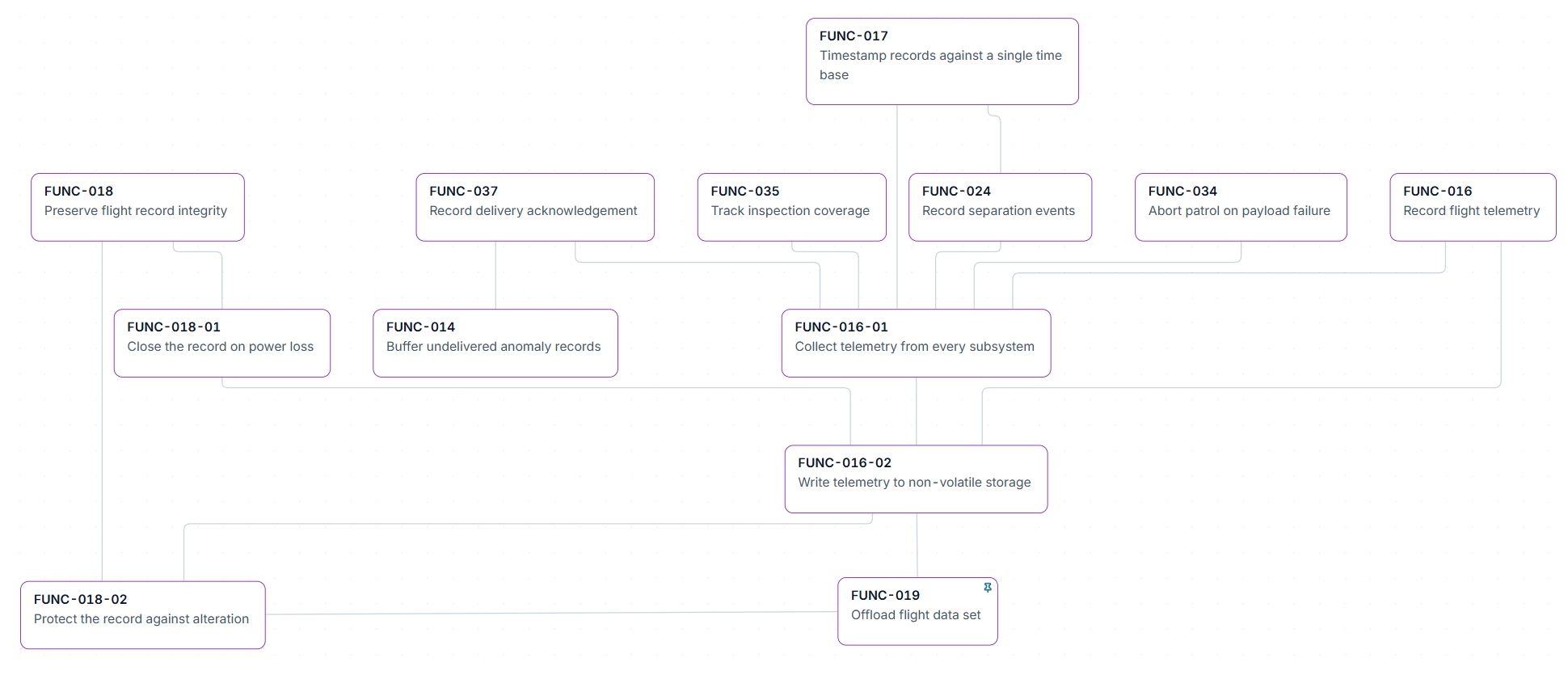
An ASYST function decomposition tree: FUNC-017, timestamp records against a single time base, above a row of six sibling functions including preserve flight record integrity and record flight telemetry, which in turn decompose into FUNC-016-01, FUNC-016-02, FUNC-018-01 and FUNC-018-02, ending at offload flight data set.
In the product: functions decomposed to an allocatable level.

05Risk read out of the model, not off a workshop wall.

Derived from thresholds, tensions, novelty and interfaces, then scored per subsystem.

  • Produces a risk register: likelihood, consequence, exposure, mitigation
  • Standard INCOSE risk management process

Model · 05 Risk register

Stage 05 model: risk registerA five by five grid of likelihood against consequence, the high-exposure corner shaded amber. Four scored risks are plotted: R-01 and R-04 in the amber zone, R-07 and R-09 lower. Each risk is scored, mitigated and attributed to a subsystem.consequence → R-01 R-04 R-07 R-09 likelihood → scored · mitigated · attributed to a subsystem

06Nothing reaches test without a way to pass it.

A method and a measurable criterion per requirement. Gaps are counted, never invented.

  • Produces a V&V matrix and the list of incomplete entries
  • Standard ISO 29148 verifiability, INCOSE V&V processes

Model · 06 V&V matrix

Stage 06 model: verification and validation matrixOne row per requirement with a method and an acceptance criterion: REQ-014 by test, drift at most 10 ms; REQ-015 by analysis, margin at least 1.4; REQ-016 by demonstration, docks unaided. REQ-017 has no criterion yet and is counted as one incomplete entry, in amber.REQ method acceptance criterion REQ-014 Test ≤ 10 ms drift REQ-015 Analysis margin ≥ 1.4 REQ-016 Demonstration docks unaided REQ-017 none not yet stated 1 INCOMPLETE counted, not hidden

07Components, and the interfaces between them, written down.

What crosses each boundary, which way, under what conditions. Cheapest to fix on paper.

  • Produces a component breakdown and a definition for every interface
  • Standard MBSE practice: physical architecture derived from the functional

Model · 07 Components and interfaces

Stage 07 model: components and interfacesFour components joined by four defined interfaces: ICD-02, data at 1 Gb/s, from compute to sensing; ICD-05, RF, both ways between power and comms; ICD-01, 28 V DC, from compute to power; ICD-07, thermal, from sensing to comms. Every boundary has a direction and conditions. COMP-001 compute COMP-004 sensing COMP-007 power COMP-012 comms ICD-02 data · 1 Gb/s ICD-05 RF · bidirectional ICD-01 28 V DC ICD-07 thermal every boundary defined · direction · conditions

08Every artefact knows where it came from.

Every link in one chain, checked both ways. Orphans are reported.

  • Produces bidirectional traceability and an explicit list of gaps
  • Standard ISO 29148 bidirectional traceability

Model · 08 Traceability
Stage 08 model: traceabilityRequirement REQ-014 traced downstream: satisfied by FUNC-021 and FUNC-022, allocated to COMP-007, verified by VV-014, and COMP-007 drives RISK-009. Every edge carries its relationship type and the chain is computed both ways. REQ-014 timestamping FUNC-021 satisfied by FUNC-022 satisfied by COMP-007 allocated to VV-014 verified by RISK-009 drives bidirectional · computed, not written
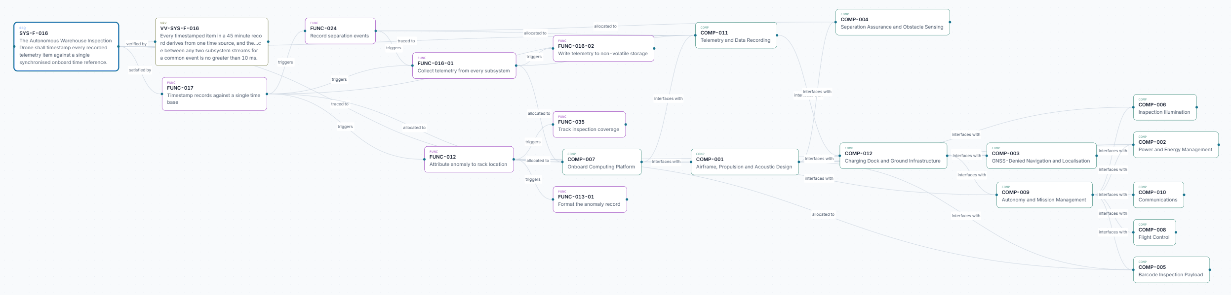
An ASYST traceability graph starting at requirement SYS-F-016, a timestamping requirement, verified by VV-SYS-F-016 and satisfied by FUNC-017, fanning right through functions FUNC-024, FUNC-016-01, FUNC-016-02, FUNC-035 and FUNC-012 into eleven components from COMP-001 to COMP-012, with each edge labelled verified by, satisfied by, triggers, traced to, allocated to or interfaces with.
In the product: one requirement and everything downstream of it.

09One document you can take into a gate review.

DOCX or PDF, with the model identifiers preserved end to end.

  • Produces the Need Analysis document
  • Standard one set of identifiers for document and model

Export becomes a Professional feature at general availability.

See the tiers

Model · 09 Need Analysis

Stage 09 model: the Need Analysis documentThe model on the left exports to a Need Analysis document with five sections, context, requirements, functions, risks and V and V, which exports on to DOCX. The document cites the same identifiers as the model, such as REQ-014 and FUNC-021. Need Analysis 1. Context 2. Requirements 3. Functions 4. Risks 5. V&V REQ-014 · FUNC-021 MODEL DOCX one set of identifiers, shared

Run the pipeline on your own brief.

Free while ASYST is in early access. One brief in, nine artefacts and the chain between them out.

Start free
Next 02Evidence

Why the model holds up when a reviewer pulls on it, and a real project you can open.